RECOBI –Renovation of complex geometry buildings with additive manufacturing–
Cyber-Physical twin prototypes –Innosuisse / Innovation Booster Additive Manufacturing (IBAM), 2024
WORK IN PROGRESS
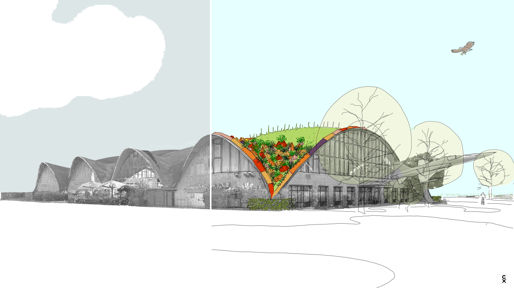
Project milestones
01 project brief [submitted: March 2024]
02 lidar survey for the cyber prototype [carried out: September 2024]
03 physical prototype [work in progress]
Funding
Innovation Booster Additive Manufacturing (IBAM), 2024
Instrument from Innosuisse
Stakeholder
– DDPS Science & Technology center: accompanying research
– DDPS Immobilien, Facility Management Ost
– Air Force Center, Dübendorf
– Coeur de Terre / Brauchli Ziegelei AG: Additive manufacturing of tiles
– Fanzun AG: building physic
– Jaquier Pointet SA: lidar documentation
– Muttoni Partners ingénieurs Conseils SA: civil engineering
– Phida Groupe: logistic & implementation
– Sika Technology AG: mycelium
– ZinCo AG: green roof systems
Special thanks to:
Fablab Renens, CEPV Vevey, COMATEC Ste-Croix
01 project brief
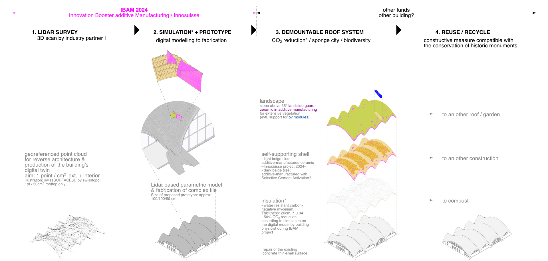
Synopsis
RECOBI aims to produce cyber-physical twin prototypes to renovate complex geometry building with additive manufacturing. The prototypes should be the proof of concept for the realisation of an isolated green roof on a hyperbolic paraboloid building.
A demonstrator will be used for this purpose: the Flieger Flab Museum in Dübendorf (ZH), a thin shell (« dome like ») building built in 1987. This shed type building was designed with four para- and hyperboloid modules by Swiss engineer Heinz Isler. In Switzerland, at least eight buildings have been constructed using these modules, mainly sports halls.
At first a Lidar based digital twin of the roof should be executed. Based on this a simulation of the roof covering should be produced. The roof covering is a multilayer which main part is an additive manufactured mineral tile. The tile protect an insulation layer and support the vegetation layer. In the steepest part of the roof, the geometry of this second mineral shell will act as protection against landslides.
As most buildings of this type are protected, the dismantling of the proposed layer should leave no trace and be replaced using future technologies -for instance, when nuclear fusion is mastered or membrane insulation is invented-.
Arguments
Many buildings from the second half of the 20th century are poorly insulated; they require a lot of energy to heat in the winter and are overheated in the summer. Currently, their renovation often incudes a layer of 15 to 20 cm insulation on their envelope –facade and roof- to reduce by 50% CO2 emissions (Energy Perspective 2050+).
Green roofs promote biodiversity and prevent flooding in the event of heavy rain (contribution to measures to promote the « sponge city » model on flood management).
RECOBI will allow the application of these two principles on para- and hyperboloid roofs.
State of the art
Additive manufacturing is been used to build entire buildings in concrete (i.e. the larges in 2022 is the Dubai municipality building, Emirates) or in ceramic with ornamental finish (i.e. the cladding of a housing gangway in Delft, NL by designed and printed Studio RAP).
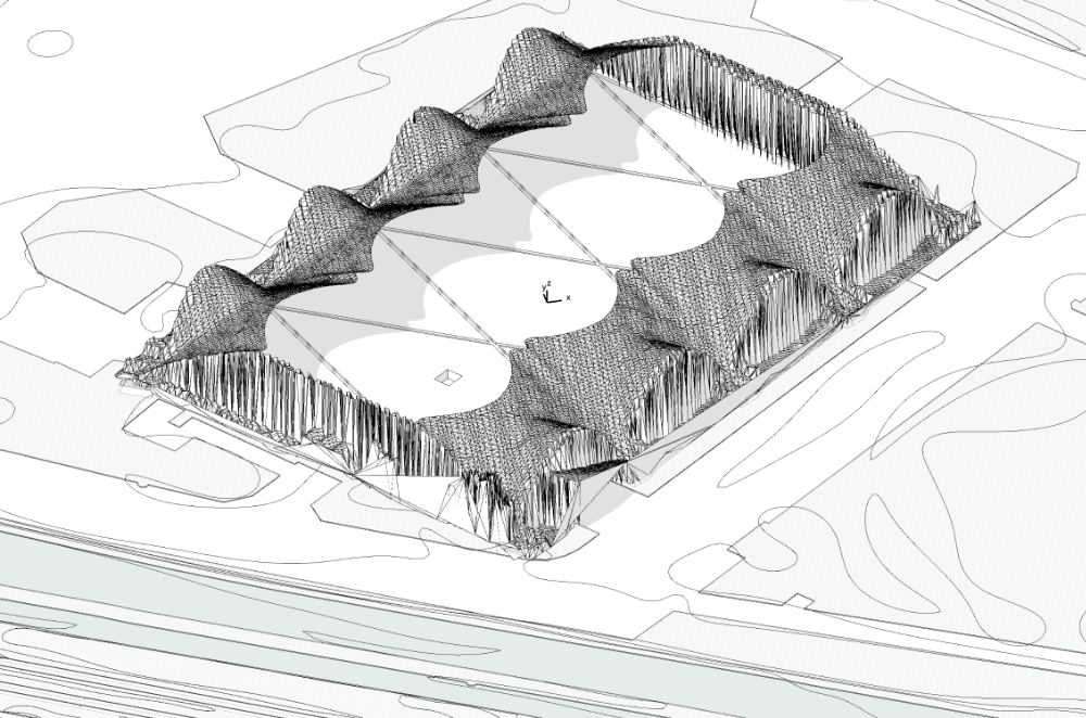
01.3. Digital model production processing Lidar data to generate 2.5D model –Delaunay triangulation– with point cloud processing software
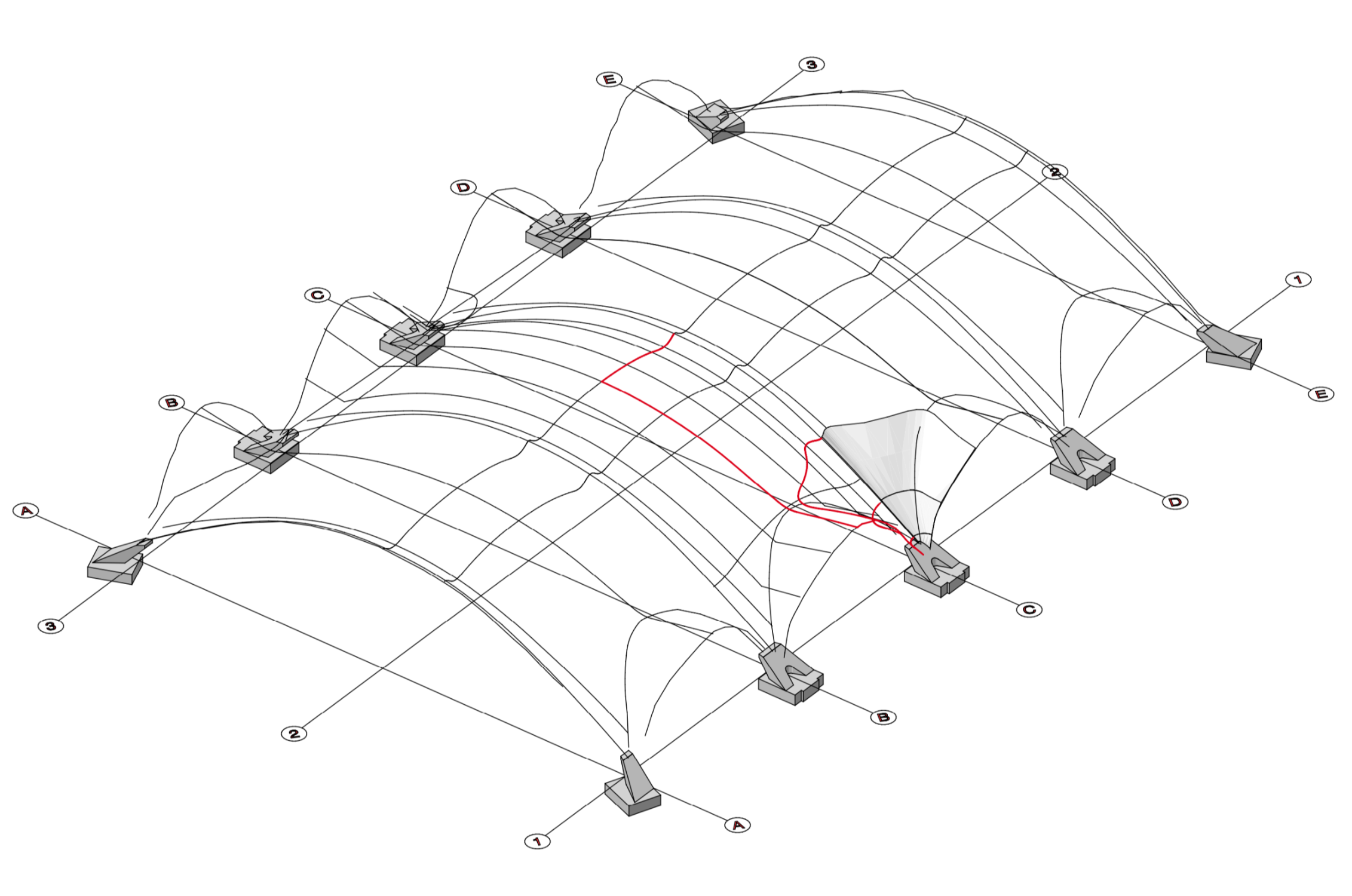
01.4. Digital model production definition of construction curves of the hyperbolic paraboloid with freeform surface modelling software
Modelling challenge to generate architectural drawings
The challenge lies in the production of a parametric model according to the Lidar documentation of the four hyperbolic paraboloid surfaces that possibly underwent a deformation. The model will be used to draw the overview of the intervention on the roof and the cutting plan of the tiles. The challenge is to keep the centimetric precision of the lidar to produce this plan.
The process of architectural plan production requires the use of three softwares: a point cloud processing software, a freeform surface modelling software and a computer aided design software (experimented on the Magnin Complex from the Swiss EXPO’64).
The point cloud is processed to generate a mesh (or 2.5D model) with the Delaunay triangulation method. This will allow to define the construction curves of the hyperbolic paraboloid to be recreated with the freeform surface modelling software (see illustrations 01.3. & 01.4. above). The reconstituted hyperbolic paraboloid surface is imported in the CAD software to complete the architectural model.
Geometric hypothesis
The four hyperbolic paraboloid thin shells of the demonstrator are in theory identical. Practically, two factors could make them unique (in masonry a tolerance of 1cm apply): 1. In over forty years the concrete shells might have undergone a deformation by compression. 2. The builders who realised them, may not have reproduced the geometry of each shell exactly.
This hypothesis is upheld by the superimposition of the digital mockup of the building on swisstopo Lidar data (approx 1 point /50 cm2). The model has an ideal geometry repeating 16 times the same fragment of the hyperbolic paraboloid. As the superimposition shows, the white patterns left on the roof –resulting of the imprecision of the model’s geometry– are not identical. This shows that the hyperbolic paraboloid might well be unique (see illustration 5. below).
With an accuracy of 1 point/cm2, the Lidar to be produced for the prototype will be able to confirm this uniqueness and this will enable the decision to be taken on how to produce the tiles.
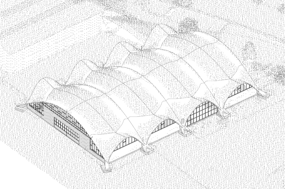
01.5. Superimposition of georeferenced Lidar data and digital model: the white patterns indicate a possible uniqueness of the thin shell modules (tool: openBIM collaborative software)
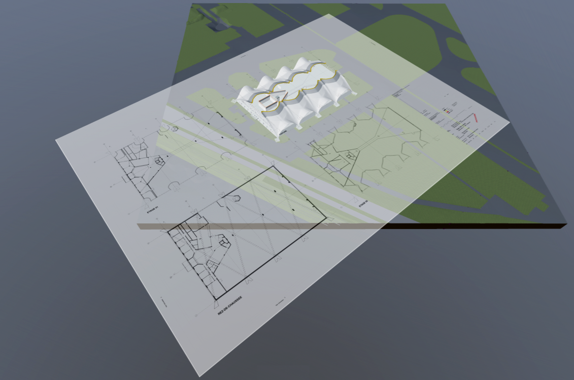
01.6. Algorithmic extraction of architect’s plan from the digital model with CAD software (illustration). Each object in the digital model must be parameterised so that its representation in the plan complies with current graphic standards
I. Cyber prototype
The additive manufactured prototype presuppose an exact documentation of the roof geometry. This will be realised by a geomatician. The point cloud he will produce will be used as reference for the making of the digital model of the building. This digital reconstruction is reverse architecture.
The covering of the entire roof will be simulated on this model and be used to design the prototype.
Alphanumerical information will be integrated in the model, such as materiality and renovation status of the objects. Architect’s plans and sections will be extracted by algorithm from the model (illustration 01.6.).
According to the definition given to a project at the ETHZ (D-Arch, Construction, Heritage and Preservation. Cherix 2023, Unpublished), the digital twin of the Flieger Flab Museum is a set of separate files describing the building with a link amongst them. Currently these files are: the digital model (containing geometry and alphanumerical information) and the Lidar data; the link is the georeference –in this case MN95–. In architecture, the digital twin must includes 2D plans as they are legal documents.
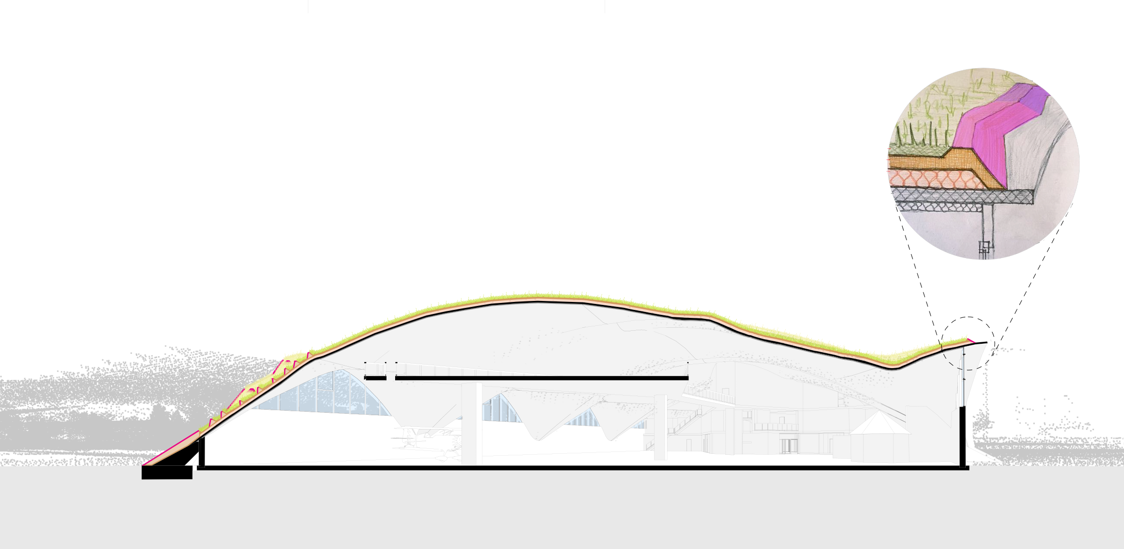
01.7. Cross-section – perspective on the building in grey the swissSURFACE3D Lidar data, in black the existing building, in colour the RECOBI project. In the section on the left, the special tiles with asperities required from 37° to retain the soil, and on the right the tile protecting the layer of insulation on the verge (inset detail)
II. Physical prototype
The RECOBI project will take full advantage of the potential to produce complex geometry building pieces with additive manufacturing as each tile covering a hyperbolic paraboloid has a different shape. The tiles are represented in beige (sections) and magenta (views), the colours are indicative.
The questions to be answer during the realisation of the prototype are: the materiality of the tile (ceramic, concrete, terra cotta), the materiality of the water resistant insulation (mycelium, hemp-plaster-lime mix, mineral foam). The definition of tiles with a standard geometry that can be produced using conventional means.
The physical prototype will be a 1m2 additive manufactured tile in-between an insulation layer and a vegetation layer. The prototype will be exhibited on the demonstrator building.
Further applications for RECOBI
Additive manufactured mineral building parts have further applications. In addition to thousands of thin-shell buildings around the world in need of renovation, representative buildings with complex geometry or ornamental feature could be completed or re-built with this technology.
02 lidar survey for the cyber prototype
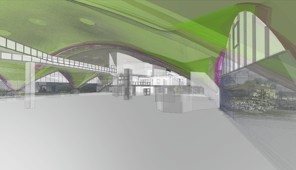
02.1 Prototype of digital twin to simulate transformation with digital model (green and magenta).
Georeferenced Lidar documentation by Jaquier Pointet SA surveyors. Definition: 1point per cm2
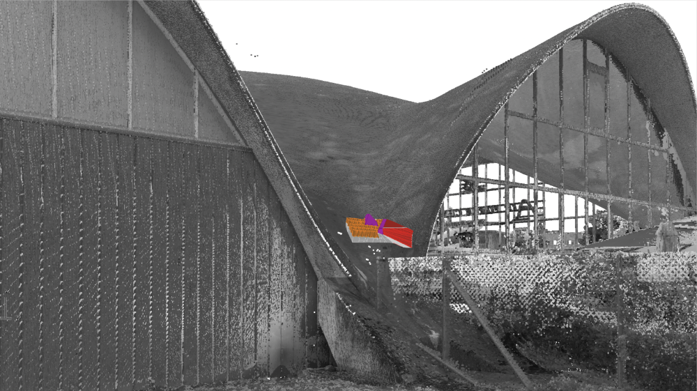
02.2 Cyber twin prototype (ceramic only) on the Lidar documentation of the building. Note: Colors on prototype are indicative.
03 additive manufacturing for the physical prototype
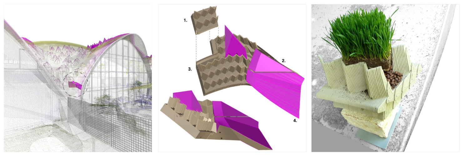
03.1 (on the left) Digital twin of the building with simulation of covering. In the middle of the circle, the prototype under construction.
03.2 (center) the one square metre ceramic part to be produced in additive manufacturing. The ceramic part was divided in four tiles. Currently, only tile 1. has been produced.
03.3 (right) Samples for the covering from top to bottom:
– Vegetation and substrate to be implemented by ZinCo
– Test of a ceramic tile in additive manufacturing, delivered unsintered and at 1/0.9 scale printed by an engineering school
– Mycelium-based insulation layer 20cm [lambda 0.04] provided by Sika
– Vapour control layer
– Existing thin shell with 6cm of insulation [lambda 0.11] on the underside (not visible on the image)