Reverse architecture of thin shell buildings
– modelling with NURBS based on point cloud for additive manufacturing – 2023
Several modern « public buildings » have been constructed using hyperboloid thin shell structures. These include the Haus der Kulturen der Welt in Berlin, the Komarovskiy market in Minsk or the 1400 structures from from Heinz Isler such as the Sicli pavilion in Geneva or the Flieger Flab Museum in Dübendorf (ZH). A number of small pavilions such as bus shelters are also build with thin shell structures.
Repairing these structures requires unique custom-made parts with complex geometries.
Lidar technology allows high precision planning, from the general geometry of the building –thanks to swisstopo datas (exemplified below)– to the detail that will enable parts to be reproduced using additive manufacturing.
Additive manufacturing makes it possible to reduce the waste generated by the production of non-orthogonal panels, i.e. door panels (see illustration below).
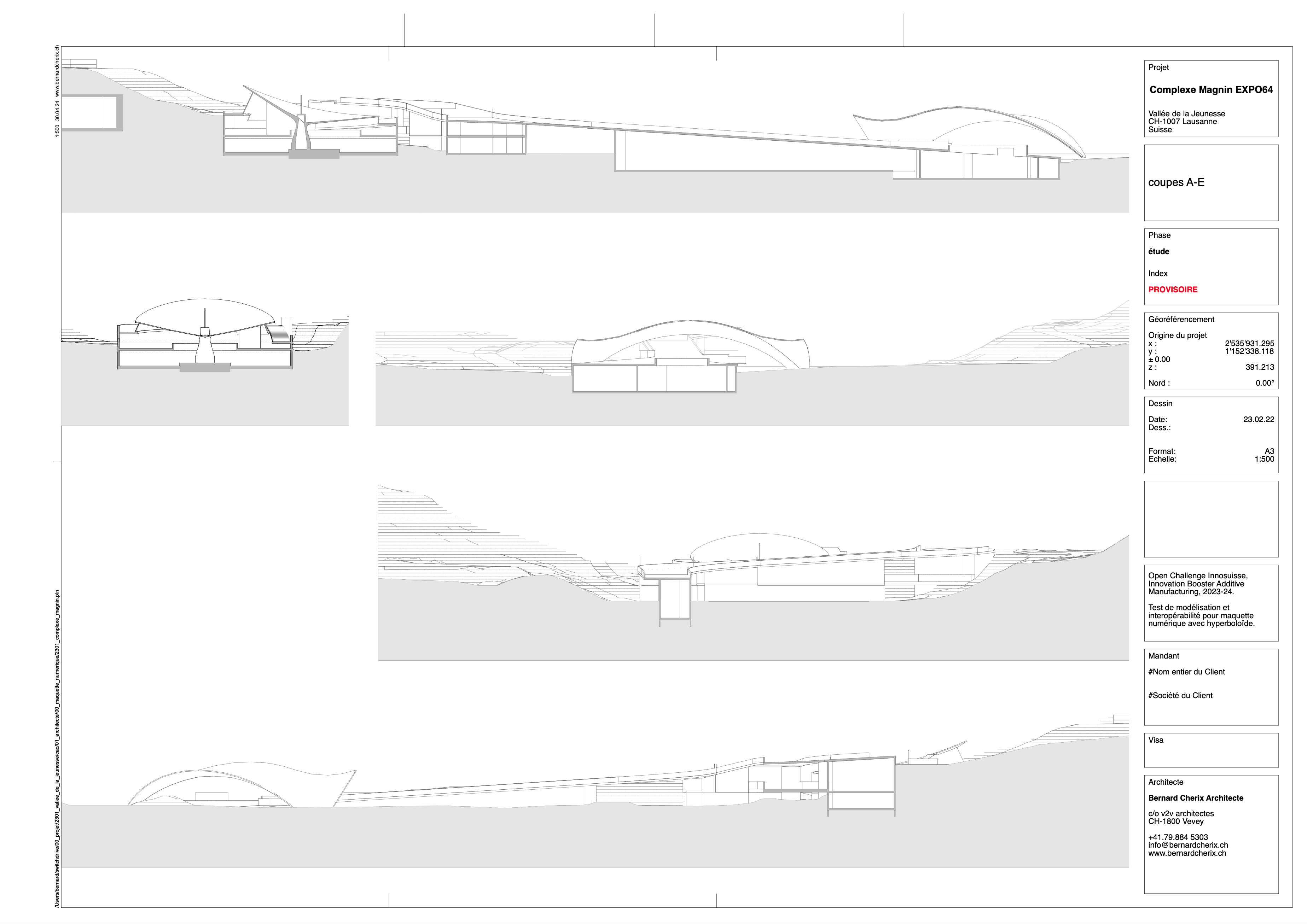
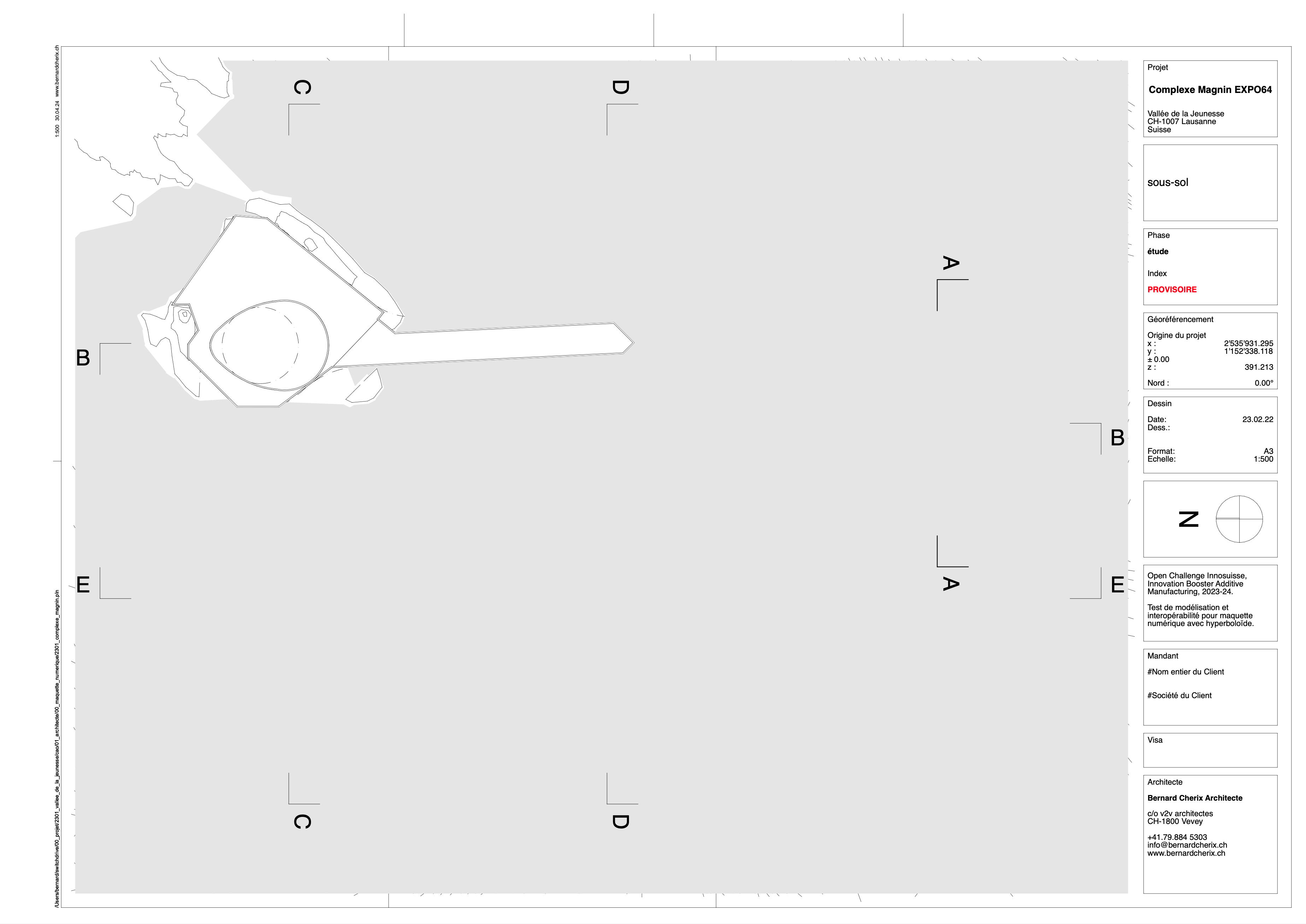
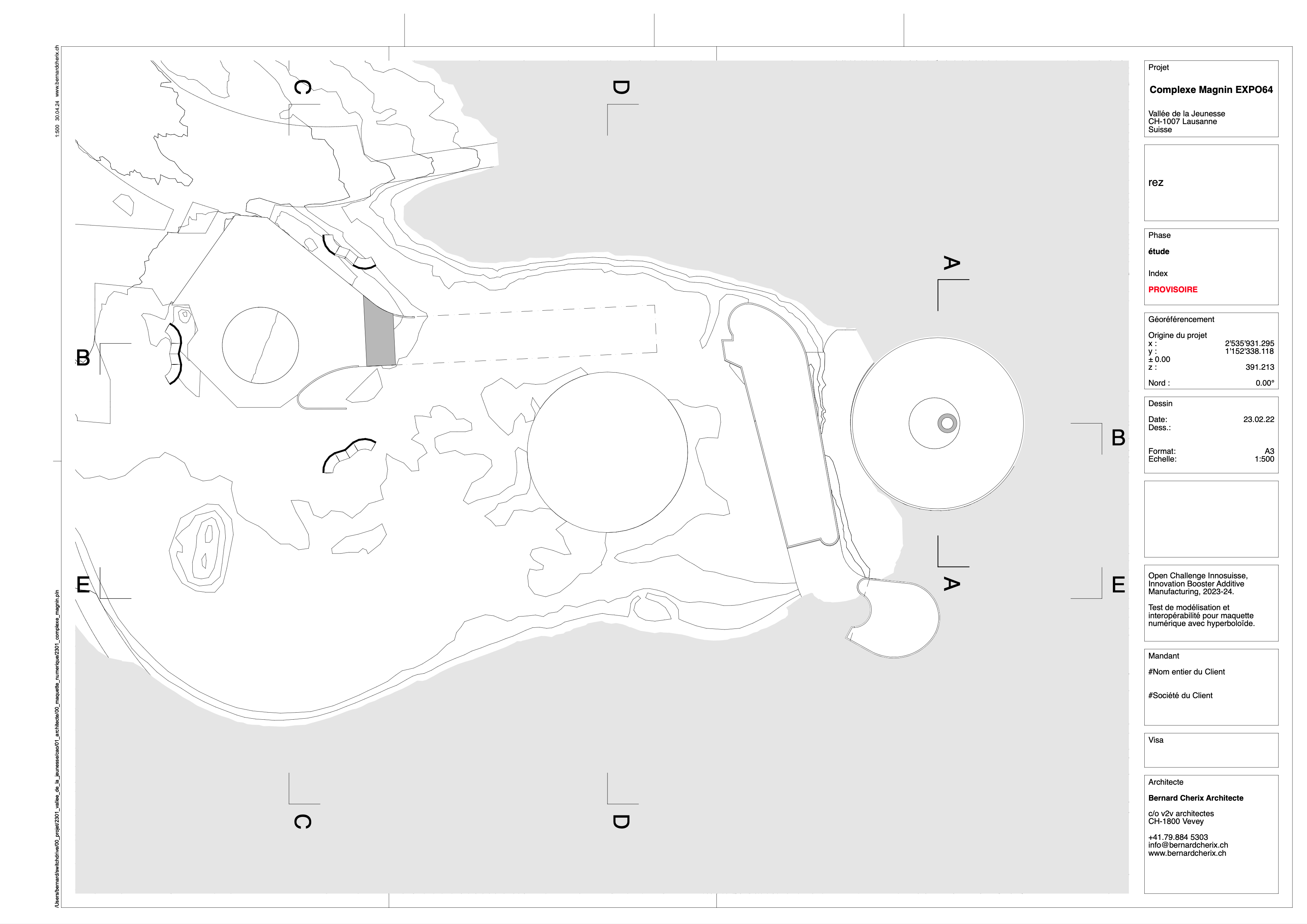
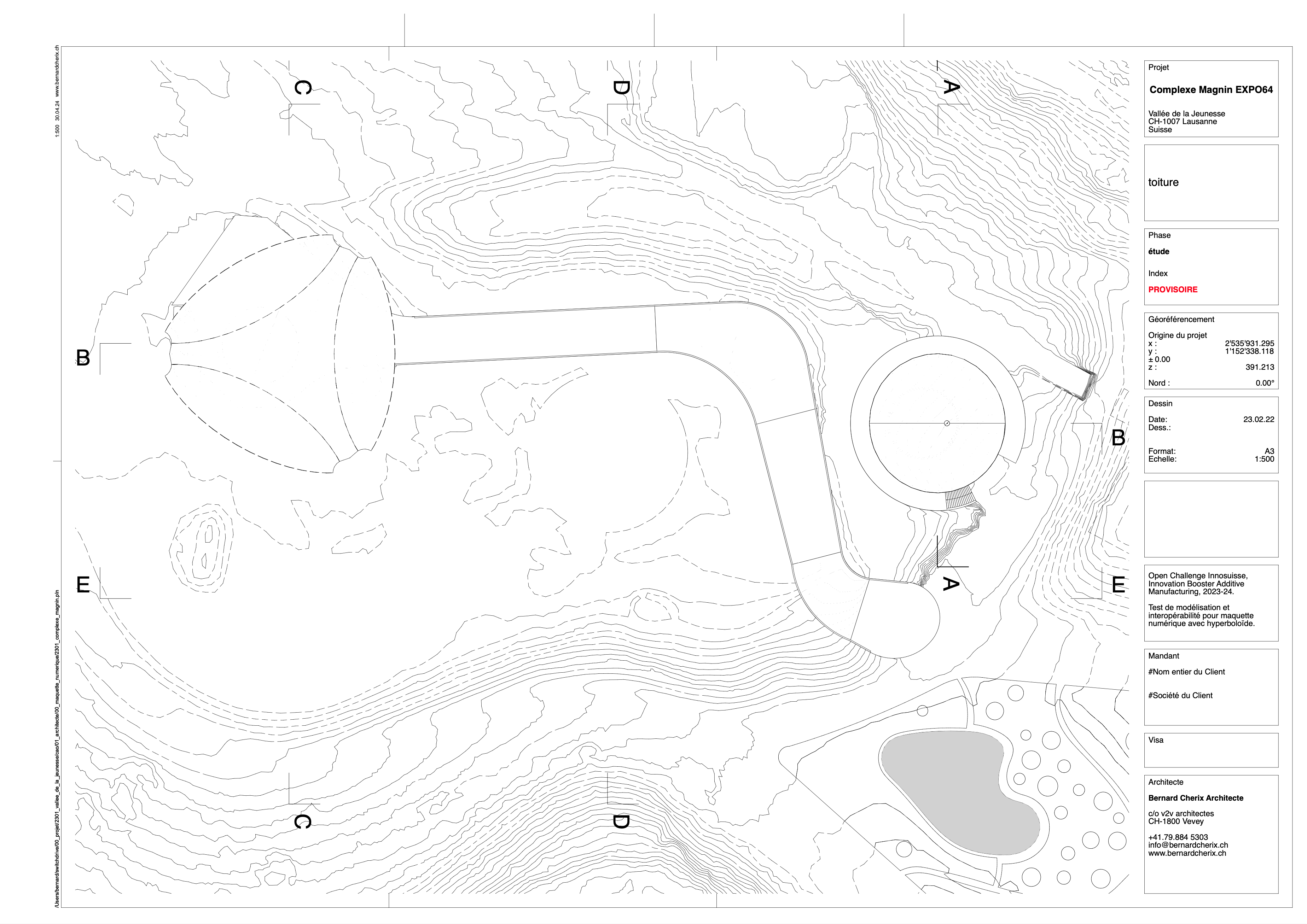
This example is based on a complex by the architect Michel Magnin –a pupil of Jean Tschumi– for the EXPO64 in Lausanne. The mockup was produced using public datas. Modelling was carried out on the roof of the second building, which is made up of several curves.
To pursue the project, an on site 3D scan will be necessary to complete the Lidar datas from swisstopo and produce a high precision mockup for additive manufacturing.
For accurate planning, the georeferencing (here in LV95) must be preserved when designing the digital mock-up, which is produced at the origin of the CAD software, i.e. close to x; y; z = 0; 0; 0.
This modelling exercise has enabled us to develop a planning method for the renovation of buildings with complex geometries, in particular those with hyperboloid envelopes. The author, together with the owner of a thin shell building and a research institute specialised on additive manufacturing, applied for an innovation grant to the Swiss Innovation Agencyy, Innosuisse..

References
– Data:
. swissSURFACE3D
. swissBUILDINGS3D
. swissALTI3D
– Tools:
. Point cloud processing software: i.e. CloudCompare
. CAD architecture: i.e. Allplan, ArchiCAD, Revit
. Freeform surface modeler (FFSM): i.e Form-Z, Rhinoceros3D
01. compilation of topographic model (.xyz) and buildings (.dxf). Photogram from Point cloud processing software

02. production of the situation mock-up with CAD software

03. first analysis of the building’s geometry (edges) in the CAD software [alternative: analysis in FFSM]

04. definition of the project origin in the CAD: surveyor point georeferenced in LV95 with altimetric accuracy

05. production of the building mockup in CAD

06. lidar data from the territory 15-20 ppt/m2

06. lidar data from the territory 15-20 ppt/m2 (close up)

07. extraction of the point cloud from the thin shell building, with point cloud processing software

08. second analysis of the building’s geometry (curves) in the CAD software [alternative: analysis in FFSM]

09. redrawing of the curves with NURBS in FFSM software

10. generating NURBS surfaces with FFSM software

Note: the NURBS surfaces are transformed in polygonal surface or mesh

12. import of the NURBS based thin shell building object in the mock-up of the complex

13. algorithmic extraction of sections from the digital mock-up

QED.


