BERGIÈRES SCHOOL COMPLEX, LAUSANNE
openBIM projects and research, 2016
Complexe scolaire des Bergières, Lausanne. Built in1977. Architects: Marx Levy, Bernard Vouga. Client: Ville de Lausanne
The Bergières school complex was built according to the principles of the Centre de Rationalisation de Construction Scolaires (CROCS, School Building Rationalisation Centre). Created in the 1960s, in the midst of the baby boom, this centre had to respond to the urgent need to build new schools.
The designers followed the modular principles defined by CROCS for the classrooms of the main part. In its socle built in masonry, they followed the structural grid from the modules but took some freedom in terms of architectural arrangements.
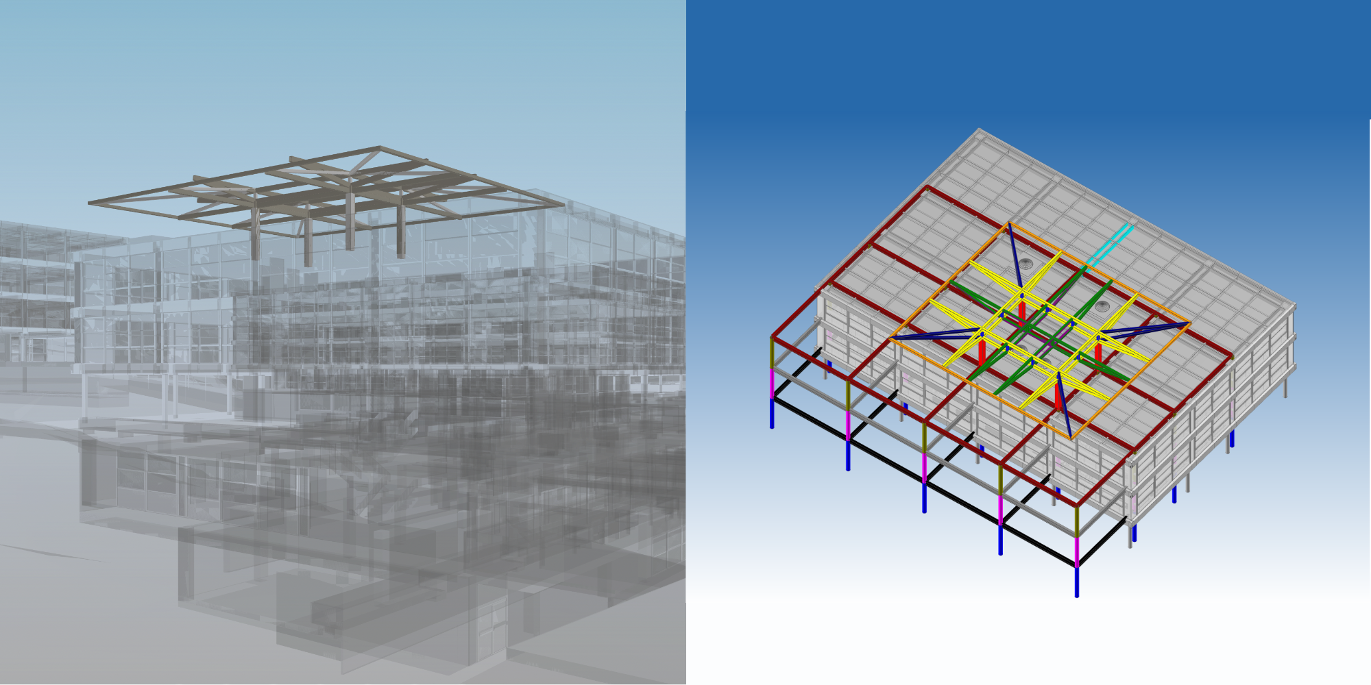
They incorporated into the spatial organisation some of the principles of the educational reforms that were also taking place at the same time. These reforms included, in particular, the reform of the mastery of French, (Maîtrise du Français) of Marie-Josèphe Besson, Pr. Bertrand Lipp [et.all] who saw for instance, classrooms for the youngest as multi-purpose and transformable spaces.
Some ten colleges were built with these principles, the one on the Bergières estate is the largest and most complex of all.
It includes: 52 classrooms, special premises (i.e. audio-visual, wood and metal workshops), a day-care centre, a sports hall, a swimming pool, a multi-purpose hall, a leisure centre and a civil protection shelter. They are distributed in five pavilions on a 33’000m2 section. The entire complex has 30’000m2 and 100’000m3.
The « openBIM » projects were linked to the eponym elective course at the EPFL 2016-17. They included the reverse architecture process for production of the digital models from the complex as well as a set of simulations. Some simulations where carried out in collaboration with civil engineers.
They are summarised below:
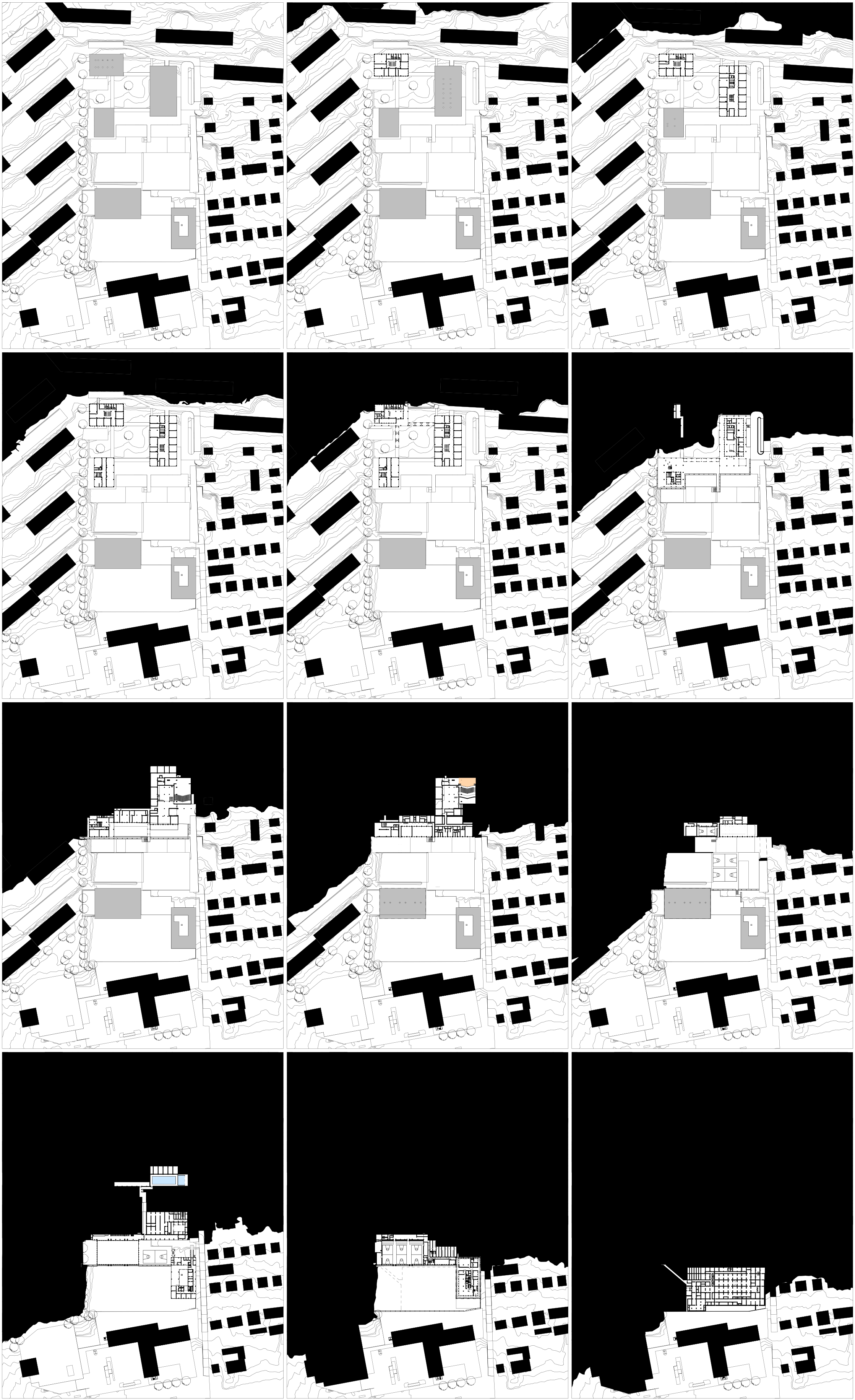
1. Reverse architecture -production of the complex digital models-
3. Simulation of shadows projections (design parameter)
4. Simulation of energy consumption: Building Energy Model (BEM)
5. Simulation of structural change –interdisciplinary modelling–

Teaching Units & Elective course EPFL 2015-2018
Assistants and scientific collaborators:
– Z.Haghparast Arch, M.Paronesso Ing., A.Rosenfeld Arch., C.Soom Ing., Dr.Zurbrügg
Digital Models, students architecture:
– Beaud, Fritzinger, Hoffmeyer, Jaquier, Joly-Pottuz, Lehmann, Perez, Richner, Vogl
Simulations and interdisciplinary projects:
– Professor civil engineering: A.Nussbaumer, RESSLAB, EPFL
– Expert in building physics: Dr. A.Kostro, LESO EPFL
– Students architecture: Bounemer, Hanssens, Hoffmeyer
– Students civil engineering: Bahr-Bruyère, Cardis, Girod, Heller, Kinnar, Lazeyras , Mattey, Realini, Sonderegger, Tijani
Cooperation with the Centre d’Enseignement Professionnel de Morges (CEPM) 2017
Exercise of modelling and federation of MEP models. G.-L.Ferrini, teacher. Ecole Supérieur Technique (ES-T)
1. REVERSE ARCHITECTURE -production of the complex digital models-
Production of digital models and research
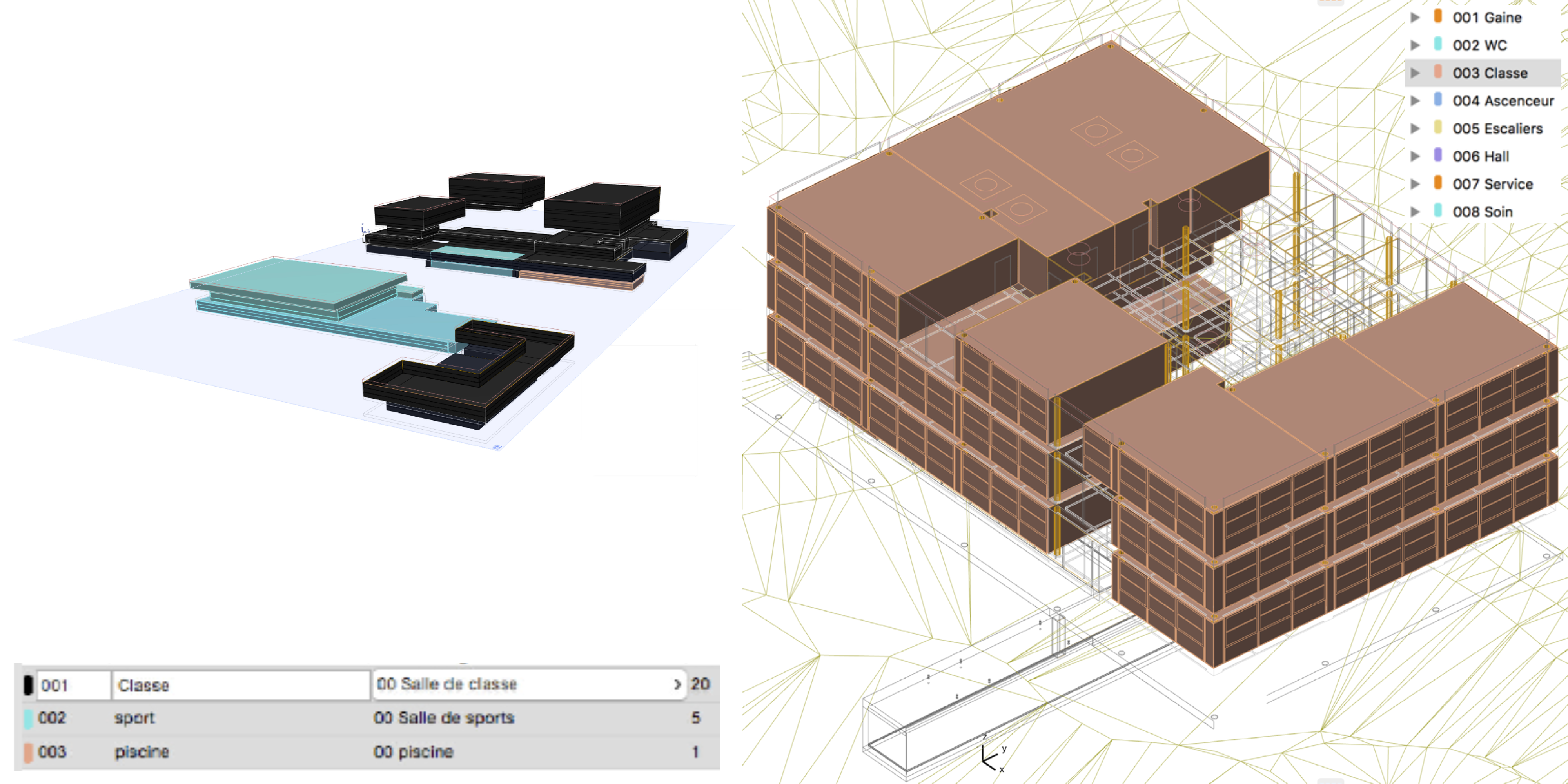
Compilation of 5 parametric models with different hight references due to topography
Research on information:
– Structuring the data of the objects constituting the digital models in relation to the floor of the building, respectively the whole complex
Research on geometry:
– Exploit the topographic models of swisstopo –meshes in .xyz– in order to obtain a parametric object including contour lines for the terrain to be modified for the project (see isometric above)

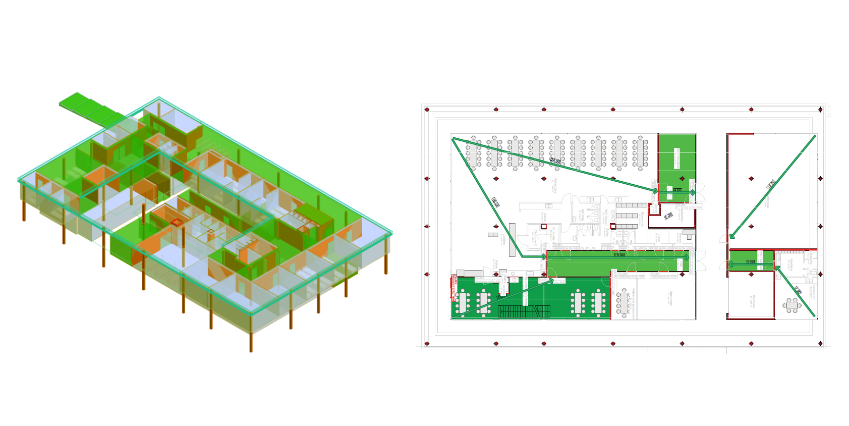
2. SIMULATION OF FIRE ESCAPE
Introduce safety-related information into the objects that make up the model:
– Spaces: unit of use / escape route
– Walls, slab, columns: fire resistance (EI 00; 30; 60; 90)
– Doors: fire resistance (E 00; 30; 60; 90)
Visualise escape routes in three dimensions and measure distances.
Algorithmic extraction of the safety plans from the digital model (right image)
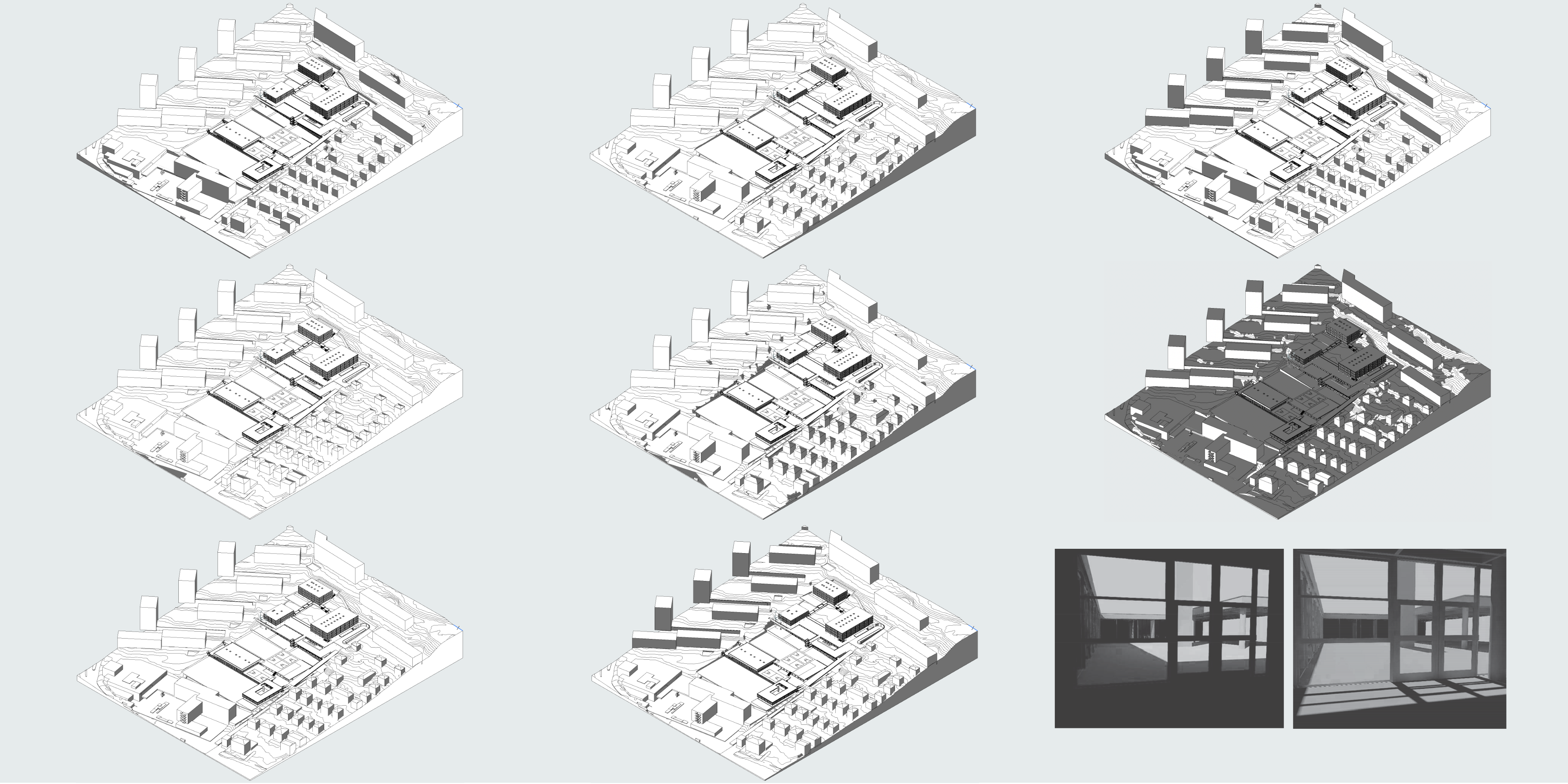
3. SIMULATION OF SCHADOWS PROJECTIONS –as re-design parameter–
Projection on solstices and equinox at specific time as impact study, to localise spaces subject to
– overheating
– dazzle
The facade of the spaces identified as problematic (illustration bottom right) will be redesigned
4. SIMULATION OF ENERGY CONSUMPTION –Building Energy Model (BEM)–
For architects, softwares for BEM are « back boxes ». They process a set of information and gives results that only experts can validate.
Nevertheless empirical and comparative studies can be made as first approach in the design process.
In this case, the result of the simulations were used to write the lecture on BEM (see Cours 10 –in French–).
Two simulations of energy consumption calculations were carried out at different scales. Both include the existing state of the building and a fictitious state after renovation of the envelope.
1. The first simulation, at the scale of the whole complex in LOD 100, used public datas on energy consumption of the complex and compared two softwares. One certified by local authorities, the other embedded in a CAD software. The certified software was used by an engineer company and provided results taken as reference for our simulation with the second software (illustration: left).
2. The second simulation, at the scale of one pavilion in LOD 300, showed how to structure the geometric and alphanumeric data of the digital model for the calculation required for the building permit with the certified software.
Currently, physicists build their own calculation model and transmit the objectives in the form of a report. Here the aim was to use the IFC format to exchange the project data between the architect’s digital model and the physicist’s calculation model (illustration: right).
It is pertinent to have a calculation model from the digital model in the case of buildings with complex geometry such as some historical monuments.
5. SIMULATIONS OF STRUCTURAL CHANGE –interdisciplinary modelling–
– With Pr. A.Nussbaumer, RESSLAB, EPFL–
Teams of students in architecture and civil engineer had to design a volume on top of the existing building and consider the typical CROCS structure (illustration left). They used a common data environment (CDE) to exchange their models in IFC and encouraged to communicate with .BCF. The illustration on the right showed two issues that the students faced in the design process:
1. The geometric differences between the structural analysis model and the architect’s model (see the double beams highlighted in blue in the model)
2. The origine of the model: while working, the position of the model can accidentally be moved. Here the origin of the project is close to the building, this becomes sensitive when the digital model is georeferenced.
A difficulty in carrying out this exercise was the lack of modelling skills of the engineers. Drawing courses have been removed from the study plan with the advent of computer-aided drawing as the machines were only capable to calculate simple shape. Today, the mastery of computer-aided design software that includes notions of artificial intelligence is all the more challenging without course.
